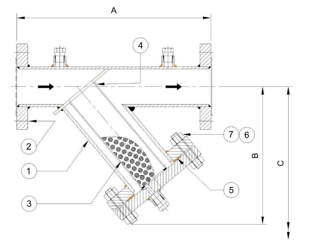
Y Type Strainer
Standard Material Data Sheet
| Part | Carbon Steel | Low Temperature CS | Stainless Steel | Monel |
| 1. Body | ASTM A 106 | ASTM A333 GR 6 | AISI 304 / 316 / 304L | Monel 400 / 500 |
| 2. Flanges | ASTM A 105 | ASTM A350 GR LS2 | AISI 304 / 316 / 304L | Monel 400 / 500 |
| 3. Screen 1 & Screen 2 | AISI 304 / 316 | AISI 304 L / 316 L | AISI 304 / 316 / 304L | Monel 400 / 500 |
| 4. Internals | AISI 304 / 316 | AISI 304 L / 316 L | AISI 304 / 316 / 304L | Monel 400 / 500 |
| 5. Gasket | CNAF / PTFE / SPW | SPW | SPW / PTFE | SPW / PTFE / CNAF |
| 6. Stud | ASTM A 193 GR. B7 | ASTM A 320 GR. L7 | ASTM A 193 GR B8 | Monel 400 / 500 |
| 7. Nut | ASTM A 194 GR.2H | ASTM A 194 GR.4 | ASTM A 194 GR. 8 | Monel 400 / 500 |
Notes: 1. Recommended Spares shall be requested along the Order 2. Screen 1 is Perforated, and Screen 2 is mesh 3. Customised according to application and materials are interchangeable at actual with respect to the availability, please enquire before order | ||||
Dimension Chart
| Size | A (±10) | B (±10) | C (approx.) Screen Removal | Weight (Kg) | |||||||||
| (NB) | 150# (mm) | 300# (mm) | 600# (mm) | 150# (mm) | 300# (mm) | 600# (mm) | 150# (mm) | 300# (mm) | 600# (mm) | 150# | 300# | 600# | |
| 25 | 200 | 230 | 280 | 128 | 150 | 180 | 230 | 250 | 260 | 2.3 | 8.0 | 16.7 | |
| 50 | 260 | 300 | 320 | 170 | 220 | 250 | 310 | 400 | 420 | 9.2 | 16.5 | 30.2 | |
| 65 | 310 | 350 | 400 | 230 | 300 | 350 | 420 | 540 | 600 | 14.5 | 20.5 | 37.0 | |
| 80 | 350 | 400 | 480 | 250 | 325 | 400 | 480 | 600 | 720 | 28.3 | 40.6 | 60.5 | |
| 100 | 400 | 460 | 520 | 305 | 390 | 450 | 590 | 680 | 800 | 41.7 | 55.1 | 81.0 | |
| 150 | 580 | 650 | 775 | 380 | 440 | 520 | 650 | 800 | 990 | 61.2 | 80.0 | 110.0 | |
| 200 | 620 | 750 | 900 | 450 | 510 | 650 | 720 | 950 | 1050 | 78.5 | 108.0 | 165.0 | |
| 250 | 726 | 980 | 1140 | 595 | 650 | 730 | 810 | 1080 | 1175 | 168.0 | 195.5 | 282.8 | |
| 300 | 850 | 1100 | 1300 | 630 | 700 | 900 | 900 | 1300 | 1500 | 350.0 | 450.0 | 520.0 | |
| 350 | 1020 | 1200 | 1415 | 710 | 900 | 1050 | 1008 | 1600 | 1760 | 390.0 | 510.0 | 750.0 | |
| 400 | 1115 | 1350 | 1520 | 790 | 1050 | 1202 | 1060 | 1800 | 2020 | 435.0 | 560.0 | 890.0 | |
| 500 | 1210 | 1500 | 1650 | 840 | 1126 | 1350 | 1100 | 1900 | 2175 | 608.0 | 670.0 | 1050.0 | |
| 600 | 1285 | 1700 | 1890 | 950 | 1250 | 1490 | 1252 | 2120 | 2300 | 749.0 | 920.0 | 1248.0 | |
| 700 | 1400 | 1900 | 2050 | 1200 | 1400 | 1605 | 1560 | 2200 | 2650 | 900.0 | 1155.0 | 1580.0 | |
| 800 | 1650 | 2100 | 2400 | 1320 | 1600 | 1800 | 1780 | 2310 | 2780 | 1200.0 | 1600.0 | 1925.0 | |
| 900 | 2200 | 2500 | 3100 | 1700 | 2000 | 2150 | 2350 | 2560 | 2899 | 1510.0 | 2025.0 | 2270.0 | |
| 1000 | 2650 | 3100 | 3700 | 2020 | 2300 | 2565 | 2710 | 2820 | 2980 | 1850.0 | 2310.0 | 2600.0 | |
| Notes: 1. Dimension are Experimented and found suitable for a standard pressure drop only, customized specifications and applications shall differ, request for a drawing post Ordering. 2. Filtration area and Free Flow Area are calculated considering the standard available Filters, customized Filters shall differ accordingly (refer following pages for calculation) | |||||||||||||
Conical Strainers / Temporary Strainers
Notes:
- Selection of Low Velocity Model (LVM) Conical Strainer for Fluid Inlet Velocity < 1 m/s
- Selection of Mid Velocity Model (MVM) Conical Strainer for Fluid Inlet Velocity 1 < 1.8 m/s
- Selection of High Velocity Model (HVM) Conical for Strainer Fluid Inlet Velocity 1.8 < 2.5 m/s
Standard Material Data Sheet
Part | Stainless Steel | Low Carbon Stainless Steel |
Flange Ring | AISI 304 / 316 | AISI 304 L / AISI 316 L |
Screen 1 | AISI 304 / 316 | AISI 304 L / AISI 316 L |
Screen 2 | AISI 304 / 316 | AISI 304 L / AISI 316 L |
Handle | AISI 304 / 316 | AISI 304 L / AISI 316 L |
Gasket | CNAF / SPW / PTFE (Optional) | SPW / PTFE (Optional) |
Notes: 1. Relevant selected spool piece with DP Gauges shall be supplied on request 2. Screen 1 is Perforated, and Screen 2 is mesh 3. Customised according to application and materials are interchangeable at actual with respect to the availability, please enquire before order
| ||
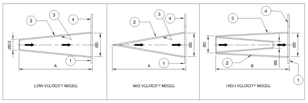
Dimension Chart
Size | A (±10) | B (±10) | C (±10) | D (±10) | E (±10) | Weight | ||
(NB) | (mm) | (mm) | (mm) | (mm) | (mm) | LVM (Kg) | MVM (Kg) | HVM (Kg) |
50 | 160 | NA | NA | 45 | NA | 1.5 | 1.1 | 2.4 |
80 | 200 | NA | NA | 72 | NA | 2.0 | 1.7 | 3.2 |
100 | 240 | NA | NA | 96 | NA | 4.5 | 3.0 | 6.3 |
125 | 280 | 300 | 75 | 120 | 20 | 7.0 | 5.8 | 9.0 |
150 | 400 | 340 | 80 | 146 | 32 | 10.8 | 8.0 | 13.6 |
200 | 520 | 480 | 100 | 197 | 40 | 16.0 | 11.9 | 19.5 |
250 | 610 | 600 | 150 | 245 | 60 | 25.0 | 20.8 | 30.7 |
300 | 680 | 680 | 160 | 295 | 72 | 31.0 | 27.6 | 36.5 |
350 | 750 | 750 | 180 | 340 | 80 | 37.0 | 33.0 | 43.0 |
400 | 900 | 925 | 200 | 390 | 88 | 41.0 | 37.8 | 47.0 |
500 | 1200 | 1200 | 240 | 492 | 95 | 46.0 | 42.0 | 53.0 |
600 | 1500 | 1500 | 280 | 595 | 110 | 58.0 | 54.0 | 65.0 |
Notes: 1. Dimension are Experimented and found suitable for a standard pressure drop only, customized specifications and applications shall differ, request for a drawing post Ordering. 2. Filtration area and Free Flow Area are calculated considering the standard available Filters, customized Filters shall differ accordingly (refer following pages for calculation) 3. Flow Direction and Filter arrangement shall be changed as per site requirements, on request 4. On change of flow direction, the dimensions are subjected to change and shall be requested by customer upon Ordering
| ||||||||
Basket Strainer
A highest efficiency strainer that allows the fluid flow with minimal restriction, thus the pressure drop across is low. Available in various maintenance free options and less maintenance options. Inline and Offline are also available, on request. Custom built if needed. Venting and Draining options available with Plugs, whereas Valves can be given on optional basis.
Basket strainers are installed upstream of equipment like pumps, control valves, traps to keep potentially corrosive or damaging debris away from making its way down the line. They can be installed alone or in a series to increase filtration. Selection of mesh size are done by our engineers precisely to be able to filter that any foreign particles are ensnared in the basket. Additionally, consider other variables such as temperature and pressure requirements, and the type of liquid or gas traversing the basket strainer.

Dimension Chart
Size | A (±10) | B (±10) | C (±10) | Weight |
|
(NB) | (mm) | (mm) | (mm) | (Kg) | |
50 | 240 | 260 | 180 | 8.9 | |
80 | 300 | 326 | 190 | 15.0 | |
100 | 340 | 380 | 210 | 20.5 | |
125 | 360 | 400 | 225 | 22.7 | |
150 | 400 | 435 | 230 | 29.9 | |
200 | 450 | 480 | 240 | 38.1 | |
250 | 500 | 600 | 325 | 59.0 | |
300 | 630 | 720 | 430 | 91.2 | |
350 | 750 | 730 | 450 | 124.0 | |
400 | 900 | 850 | 450 | 160.0 | |
Note: Dimension and Weight represented for End Connection of ANSI B 16.5 – 150# only, for Higher Pressure / Temperature applications, please request for details. | |||||
Standard Material Data Sheet
Part | Carbon Steel | Low Temperature CS | Stainless Steel |
1. Body | ASTM A 106 | ASTM A333 GR 6 | AISI 304 / 316 / 304L |
2. Inlet & Outlet Flanges | ASTM A 105 | ASTM A350 GR LS2 | AISI 304 / 316 / 304L |
3. Inlet and Outlet Pipes | ASTM A 106 | ASTM A333 GR 6 | AISI 304 / 316 / 304L |
4. Body Ring Flange | ASTM A 105 | ASTM A350 GR LS2 | AISI 304 / 316 / 304L |
5. Body Cover Flange | ASTM A 105 | ASTM A350 GR LS2 | AISI 304 / 316 / 304L |
6. Filter Plate | AISI 304 / 316 | AISI 304 L / 316 L | AISI 304 / 316 / 304L |
7. Filter Assembly | AISI 304 / 316 | AISI 304 L / 316 L | AISI 304 / 316 / 304L |
8. Bottom Cover | ASTM A 105 | ASTM A350 GR LS2 | AISI 304 / 316 / 304L |
9. Drain & Vent Plugs | ASTM A 105 | ASTM A350 GR LS2 | AISI 304 / 316 / 304L |
10. Fasteners | ASTM A 193 GR. B7 / A 194 GR.2H | ASTM A 320 GR. L7 / A 194 GR.4 | ASTM A 193 GR B8 / A 194 GR. 8 |
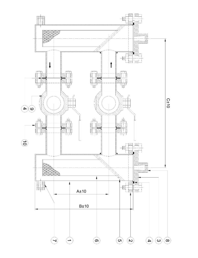
Duplex Strainer
The duplex strainer system consists of two separate strainer baskets housings. The system also contains a valve handle placed between the two baskets to divert the flow of liquid to one strainer while the other is being cleaned.
Duplex basket-type strainers are installed for continuous flow applications where the process can’t be shut down for cleaning. One chamber works and the other chamber is cleaned at the same time, ensuring the downtime to zero. Designs consist of inlet a single inlet and outlet with top accessible covers for each strainer allowing easy access to the inner strainer. The central manifold houses a lever enabling control of fluid flow to each side, and closing of each side for maintenance.
Dimension Chart
Size | A (±10) | B (±10) | C (±10) | Weight |
|
(NB) | (mm) | (mm) | (mm) | (Kg) | |
50 | 260 | 360 | 210 | 20.0 | |
80 | 326 | 430 | 300 | 42.0 | |
100 | 380 | 500 | 340 | 54.0 | |
125 | 400 | 610 | 410 | 59.0 | |
150 | 435 | 750 | 525 | 91.8 | |
200 | 480 | 850 | 600 | 150.2 | |
250 | 610 | 1000 | 950 | 202.0 | |
300 | 750 | 1250 | 1230 | 244.0 | |
350 | 850 | 1400 | 1450 | 310.0 | |
400 | 950 | 1450 | 1600 | 500.0 | |
Note: Dimension and Weight represented for End Connection of ANSI B 16.5 – 150# only, for Higher Pressure / Temperature applications, please request for details. | |||||
Standard Material Data Sheet
Part | Carbon Steel | Low Temperature CS | Stainless Steel |
1. Body | ASTM A 106 | ASTM A333 GR 6 | AISI 304 / 316 / 304L |
2. Body Ring Flange | ASTM A 105 | ASTM A350 GR LS2 | AISI 304 / 316 / 304L |
3. Body Cover Flange | ASTM A 105 | ASTM A350 GR LS2 | AISI 304 / 316 / 304L |
4. Gasket | Non-Asbestos | PTFE | PTFE |
5. Filter Plate | AISI 304 / 316 | AISI 304 L / 316 L | AISI 304 / 316 / 304L |
6. Filter Assembly | AISI 304 / 316 | AISI 304 L / 316 L | AISI 304 / 316 / 304L |
7. Drain Plugs | ASTM A 105 | ASTM A350 GR LS2 | AISI 304 / 316 / 304L |
8. Vent Plugs | ASTM A 105 | ASTM A350 GR LS2 | AISI 304 / 316 / 304L |
9. Diverting Valves | ASTM A 105 | AISI 304 | AISI 304 |
10. Fasteners | ASTM A 193 GR. B7 / A 194 GR.2H | ASTM A 320 GR. L7 / A 194 GR.4 | ASTM A 193 GR B8 / A 194 GR. 8 |
Suction Diffuser
Dimension Chart
Size | A (±10) | B (±10) | C (±10) | Weight |
|
(NB) | (mm) | (mm) | (mm) | (Kg) | |
50 | 120 | 150 | 100 | 20.0 | |
80 | 138 | 210 | 125 | 31.0 | |
100 | 160 | 320 | 160 | 44.0 | |
125 | 220 | 400 | 200 | 48.5 | |
150 | 310 | 460 | 240 | 61.2 | |
200 | 346 | 500 | 300 | 75.0 | |
250 | 400 | 650 | 350 | 91.0 | |
300 | 450 | 780 | 400 | 134.0 | |
350 | 480 | 800 | 420 | 155.0 | |
400 | 500 | 850 | 430 | 170.0 | |
Note: Dimension and Weight represented for End Connection of ANSI B 16.5 – 150# only, for Higher Pressure / Temperature applications, please request for details. | |||||
Standard Material Data Sheet
Part | Carbon Steel / Cast Steel | Low Temperature CS | Stainless Steel |
1. Inlet Flange | ASTM A 106 / ASTM A 216 WCB | ASTM A333 GR 6 | AISI 304 / 316 / 304L / CF8 / CF3 |
2. Inlet Pipe | ASTM A 106 / ASTM A 216 WCB | ASTM A333 GR 6 | AISI 304 / 316 / 304L/ CF8 / CF3 |
3. Body | ASTM A 106 / ASTM A 216 WCB | ASTM A333 GR 6 | AISI 304 / 316 / 304L/ CF8 / CF3 |
4. Filter Assembly | AISI 304 / 316 | AISI 304 L / 316 L | AISI 304 / 316 / 304L |
5. Body Ring Flange | ASTM A 105 / ASTM A 216 WCB | ASTM A350 GR LS2 | AISI 304 / 316 / 304L / CF8 / CF3 |
6. Body Cover Flange | ASTM A 105 / ASTM A 216 WCB | ASTM A350 GR LS2 | AISI 304 / 316 / 304L / CF8 / CF3 |
7. Gaskets | Non Asbestos | PTFE | PTFE |
8. Fasteners | ASTM A 193 GR. B7 / A 194 GR.2H | ASTM A 320 GR. L7 / A 194 GR.4 | ASTM A 193 GR B8 / A 194 GR. 8 |
9. Outlet Flange | ASTM A 106 / ASTM A 216 WCB | ASTM A333 GR 6 | AISI 304 / 316 / 304L / CF8 / CF3 |
10. Drain Plug | ASTM A 105 | ASTM A350 GR LS2 | AISI 304 / 316 / 304L |
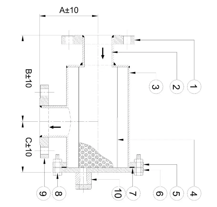
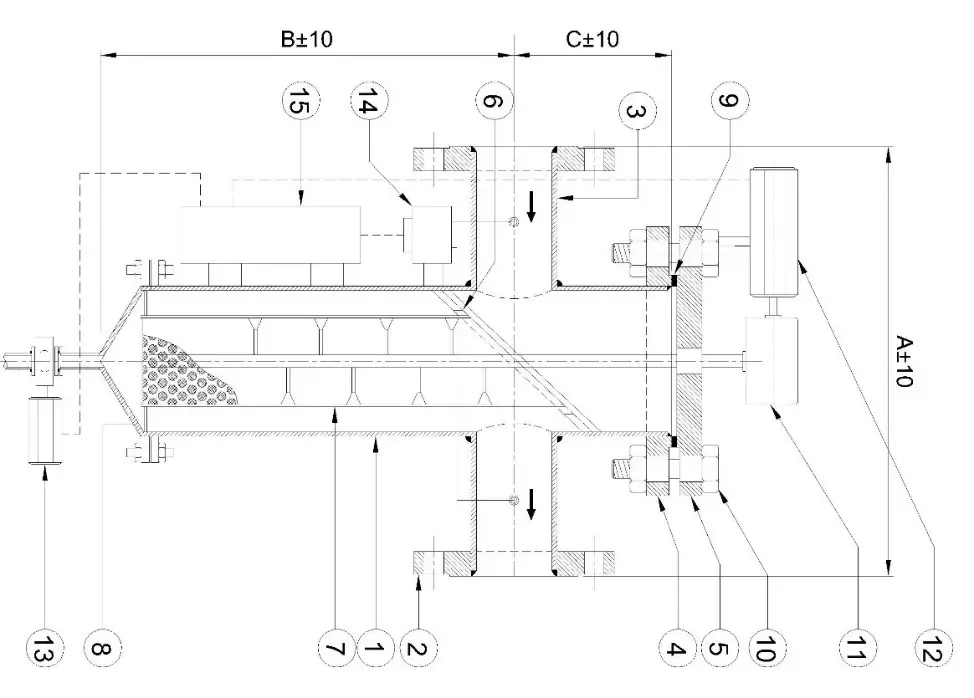
Self-Cleaning Strainers
SSTR-V18 uses motorized, automatic, self cleaning strainer provides continuous debris removal from fluid piping systems that demand full time uninterrupted flow which can be installed in an horizontal line and the sealing system is designed to perform no Leak proof in high pressure application also. Our Engineering and Designing capability allows to Develop Custom Built Automatic Strainers that can solve the requirements of different process, flow, debris, application and working pressure and temperature.
Types of Self Cleaning Strainers
1. Auto-Backwash Strainer (AB)
2. Auto-Cleaning Strainer (SC)

Dimension Chart
Size | A (±10) | B (±10) | C (±10) | Weight |
|
(NB) | (mm) | (mm) | (mm) | (Kg) | |
50 | 240 | 320 | 180 | 10.0 | |
80 | 300 | 350 | 190 | 20.0 | |
100 | 340 | 400 | 210 | 23.0 | |
125 | 360 | 450 | 225 | 29.5 | |
150 | 400 | 480 | 230 | 35.0 | |
200 | 450 | 500 | 240 | 41.0 | |
250 | 500 | 650 | 325 | 65.0 | |
300 | 630 | 780 | 430 | 101.0 | |
350 | 750 | 800 | 450 | 134.0 | |
400 | 900 | 920 | 450 | 170.0 | |
Note: Dimension and Weight represented for End Connection of ANSI B 16.5 – 150# only, for Higher Pressure / Temperature applications, please request for details. | |||||
Standard Material Data Sheet
Part | Carbon Steel | Low Temperature CS | Stainless Steel |
1. Body | ASTM A 106 | ASTM A333 GR 6 | AISI 304 / 316 / 304L |
2. Inlet & Outlet Flanges | ASTM A 105 | ASTM A350 GR LS2 | AISI 304 / 316 / 304L |
3. Inlet and Outlet Pipes | ASTM A 106 | ASTM A333 GR 6 | AISI 304 / 316 / 304L |
4. Body Ring Flange | ASTM A 105 | ASTM A350 GR LS2 | AISI 304 / 316 / 304L |
5. Body Cover Flange | ASTM A 105 | ASTM A350 GR LS2 | AISI 304 / 316 / 304L |
6. Filter Plate | AISI 304 / 316 | AISI 304 L / 316 L | AISI 304 / 316 / 304L |
7. Filter Assembly | AISI 304 / 316 | AISI 304 L / 316 L | AISI 304 / 316 / 304L |
8. Bottom Cover | ASTM A 105 | ASTM A350 GR LS2 | AISI 304 / 316 / 304L |
9. Gasket | Non-Asbestos / PTFE | SPW | SPW |
10. Fasteners | ASTM A 193 GR. B7 / A 194 GR.2H | ASTM A 320 GR. L7 / A 194 GR.4 | ASTM A 193 GR B8 / A 194 GR. 8 |
11. Gear Assembly | Carbon Steel | ASTM A333 GR 6 | AISI 304 |
12. Scrubber Motor | Carbon Steel | ASTM A333 GR 6 | AISI 304 |
13. Drain Motor | Carbon Steel | ASTM A333 GR 6 | AISI 304 |
14. PLC Controller | Carbon Steel | ASTM A333 GR 6 | AISI 304 |
15. DP Switch | (STD) | (STD) | (STD) |
Foot Valve Strainer
FVS-V19 offers wide range of application and types. Choosing the right type for the right application is tedious, we recommend the application at suction with a considerable heads over the same. Size of FVS product range from 3/8” through 36” in several different models. The purpose of a foot valve is to maintain pump prime between pumping cycles. A strainer prevents debris from entering the piping system. Foot valves are designed to minimize head loss and optimize pumping efficiency.
Foot Valve Strainer is typically placed at the lower end of the suction pipe of a centrifugal pump to prevent the suction pipe from emptying while the pump is at rest; consequently, when the pump is first started it does not have to exhaust the air from the suction pipe with the result that prompt starting of the pump is secured. Foot valve is particularly useful when the suction lift or vertical height of the pipe is considerable.
Installation:
- Inexpensive way to maintain pump prime
- Designed for installation at the bottom of a pump suction line, inside a wet well
- Ensure manually that the valve operates smoothly
- Charge the pipeline with water and Ensure that there is no leakage through flange gaskets.
- Maximum flow velocity in the pipe-line should not exceed 4 m/s.
FVS-V19-01

FVS-V19-02
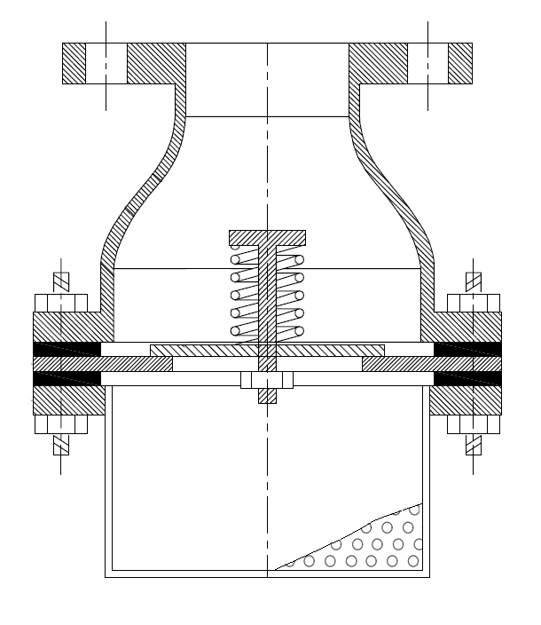
FVS-V19-03

Standard Material Data Sheet
Model | FVS-V19-01 | FVS-V19-02 | FVS-V19-03 |
Material of Composition | CS / SS / Brass | CS / SS | Cast Steel / Cast Iron |
Body | CS / SS / Brass / Other available on request | CS / SS – Galvanized | CS / CI |
End Connection | Screwed / Threaded | Flanged / Clamped | Flanged / Custom Designed |
Flange | NA | CS / SS – Galvanized | CS / CI |
Filter | SS / Brass | SS304 / SS316 | SS304 / SS316 |
Seats and Discs | SS / Brass | SS | CS / SS |
Set Screw | SS / Brass | SS | NA |
Fasteners | CS / SS | CS / SS | CS |
Support Internals | SS304 / SS316 | SS 304 / SS316 | SS304 / SS316 |
Type | Disc / Float | Disc / Flapper | Disc / Flapper |
Spring | Spring Steel / Custom Material | SS 304 | Spring Steel |
Heads | 2 MWC | 7 MWC | 12 MWC |
Design Pressure | Custom Designed | Custom Designed | Upto 10 kg/cm2 (g) |
Design Temperature | 8 to 50 Deg C | 8 to 100 Deg C | Custom Designed |
Sealings | PTFE / SPW / EPDM | PTFE & SPW | PTFE & SPW |
Flow Rate | Upto 3 m/s velocity | Custom Designed | Custom Designed |
As a continuous improvement process, the data in the table may differ with the actual product, ask for a GAD post ordering to ensure your requirement is matched. | |||